Motor Control Board
This page explains the main control and power switch boards.
Full PCB Layout
Finding The Firmware Version Info For Your Robot
Open a SSH window to your robot. The 2 items of interest are Firmware Version and Firmware Date
rostopic echo /diagnostics | grep -A 1 'Firmware [DV]'
Firmware Release Versions
The table below shows the default and latest available versions of firmware.
The Rate in the table is the rate at which the MCB STATUS led will blink which is a handy visual check. It is best to count the time of 4 or more blinks then divide by that number for accuracy. If the blink rate is found to differ from the table, it is possible you have a beta or non-approved version.
DateCode use started around version v35 and shows up in the /diagnostics topic along with the version. DateCode is in YYYYMMDD format for releases and YYMMDD for beta releases. It is the date of that particular version. If you have a version that the date is before the date in the table it is likely a Beta or unofficial release. DateCode did not start till around v35.
| Ver | Rate | DateCode | Description |
|---|---|---|---|
| v28 | 6.0 | NA | Depreciated Production shipment version that does wheel movement check on startup. Users should do a firmware upgrade from this very old version |
| v32 | 5.0 | NA | Depreciated Production firmware used in 2019. |
| v35 | 4.0 | 20190815 | Last well known good release as of Sept 2020 with double resolution wheel encoders and many improvements. Requires host side software update done after 11/10/2019 |
| v37 | 4.75 | 20200620 | Use in manufacturing only. 1st with a selftest. |
| v38 | 5.25 | 20201006 | Depreciated Beta release for some fixes. |
| v39 | 5.5 | 20201129 | Non-Magni release for in development 4wheel drive unit |
| v40 | 5.75 | 20201209 | Magni current release for most recent release candidate. This is the default if just an enter is done when asking for version |
| v43 | 4.0 | 20210829 | Magni beta release with some fixes and minor new abilities |
See: Master Controller Board Firmware and Hardware Revision History.
Checking ROS /diagnostics Topic For Firmware
The firmware version and release date are published from the motor_node to ther ROS topic /diagnostics
Invoke the following command for a couple seconds, then use Control-C to stop the scrolling output. Scroll back and look for "Firmware Version" and "Firmware Date"
rostopic echo /diagnostics
See: Firmware Upgrade (MCB) for a guide on upgrading the firmware.
Board Revision Identification
This page describes how to identify board Revisions used in the Magni robot.
- Raspberry Pi Host Computer, click here to see Pi versions/revisions
- Main Control Board (MCB)
- Switch Board (ESTOP & Power)
Main Control Board Identification
All of the Main Control Boards, also called the MCB, have a version number on the top of the board printed along the left edge of the PC board.
Prior to rev 5.2 the version number is very hard to read; we supply pictures to help with board version identification prior to rev 5.2
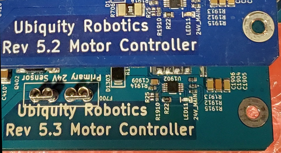
Revision 5.2 And Later Main Control boards
Starting with version 5.2 the large text for the board revisions are printed in bright white silkscreen on the left edge of the board. This page will not describe physical differences to identify the boards because the board revision is clearly marked. Below shows rev 5.2 and rev 5.3 left edge markings.
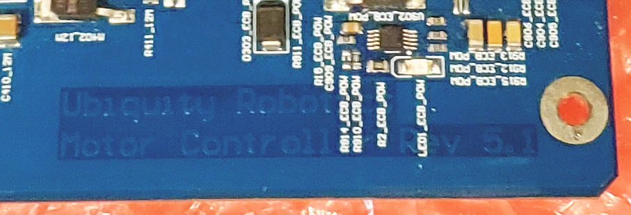
Revision Markings On Rev 5.1 and earlier
All MCB boards have the revision on the left edge of the PCB but bright white silkscreen was only started to be used as of rev 5.2. Below is an enhanced picture of a rev 5.1 board to better show what is there. These markings are very low contrast but are present on all MCB boards.
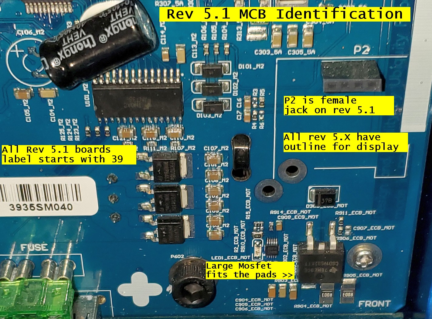
Revision 5.1 Main Control Board
Starting with revision 5.1 the rev is also shown on the top silkscreen under the large text of Ubiquity Robotics. This text is normally under the Raspberry Pi controller and so was hard to see.
The following items identify a rev 5.1 board.
- The white label with board serial number on the top will start with 39 (2019)
- Mid right edge of the board will have a 1.4 inch square outline for a display
- The P2 jack in mid right will be black plastic female 4-pin jack
- A thick white strip is on the right edge for notes as required.
- The large black MosFet transistor in lower right will fit the pads on the PC board.
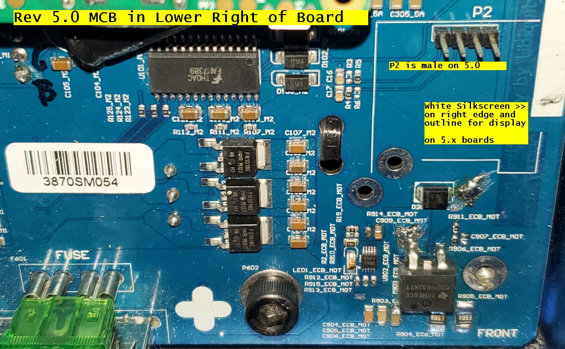
Revision 5.0 Main Control Board
These items identify a rev 5.0 board besides the top copper board rev in bottom left.
- The white label with board serial number on the top will start with 38 (2018)
- Mid right edge of the board will have a 1.4 inch square outline for a display
- The P2 jack in mid right will be a 4-pin male header
- A thick white strip is on the right edge for notes as required.
- The upper left of the board will have a large capacitor on its side with white glue
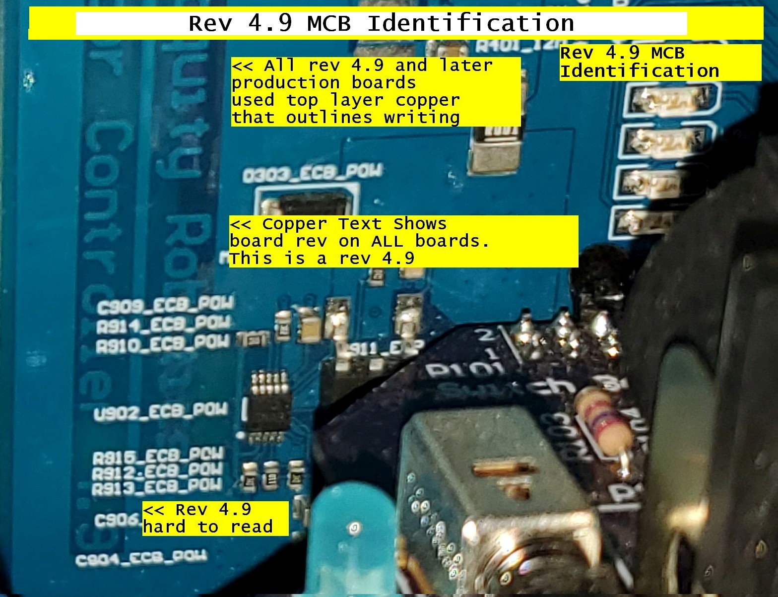
Revision 4.9 Main Control Board
These items identify a rev 4.9 board besides the top copper board rev in bottom left.
- It has no serial number stick-on tag like all rev 5.x boards will have on the MCB
- No white stripe of top silkscreen along the right edge and it has not P2 there either
- The top layer text on the left will be bordered by top layer full copper PC layer.
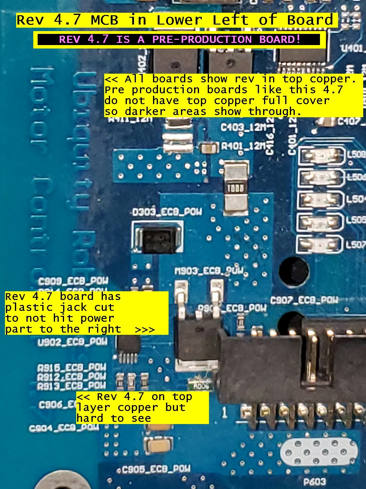
Revision 4.7 Main Control Board
These items identify a rev 4.7 board besides the top copper board rev in bottom left. THE REV 4.7 BOARD WAS A PRE-PRODUCTION BOARD FOR EVALUATION
- It has no serial number stick-on tag
- No white stripe of top silkscreen along the right edge and it has not P2 there either
- The board has not top layer of copper so large areas much darker than other areas will show through the top of the board and the text on the far left will not seem to be ‘boxed’ in copper.
- The 14-pin jack that holds the switch board had to be cut to not hit a large transistor.
- The large 50-pin jack in upper right will be a female jack for this pre-production board
Switch Board (ESTOP & Power) Revision Identification
There were several versions of switch boards from pre-production through first shipment of units using the rev 4.9 MCB. The revision number only started to appear on rev 2.0 switch boards shipped at the time of the rev 5.0 MCB boards.
Switch Boards With Remote Switch Connectors
In order to support user needs to place the main power switch and/or the ESTOP switch in a location that is on their robot cover or perhaps is more accessible due to the customer physical additions we developed the revision 2.2 switch board seen below
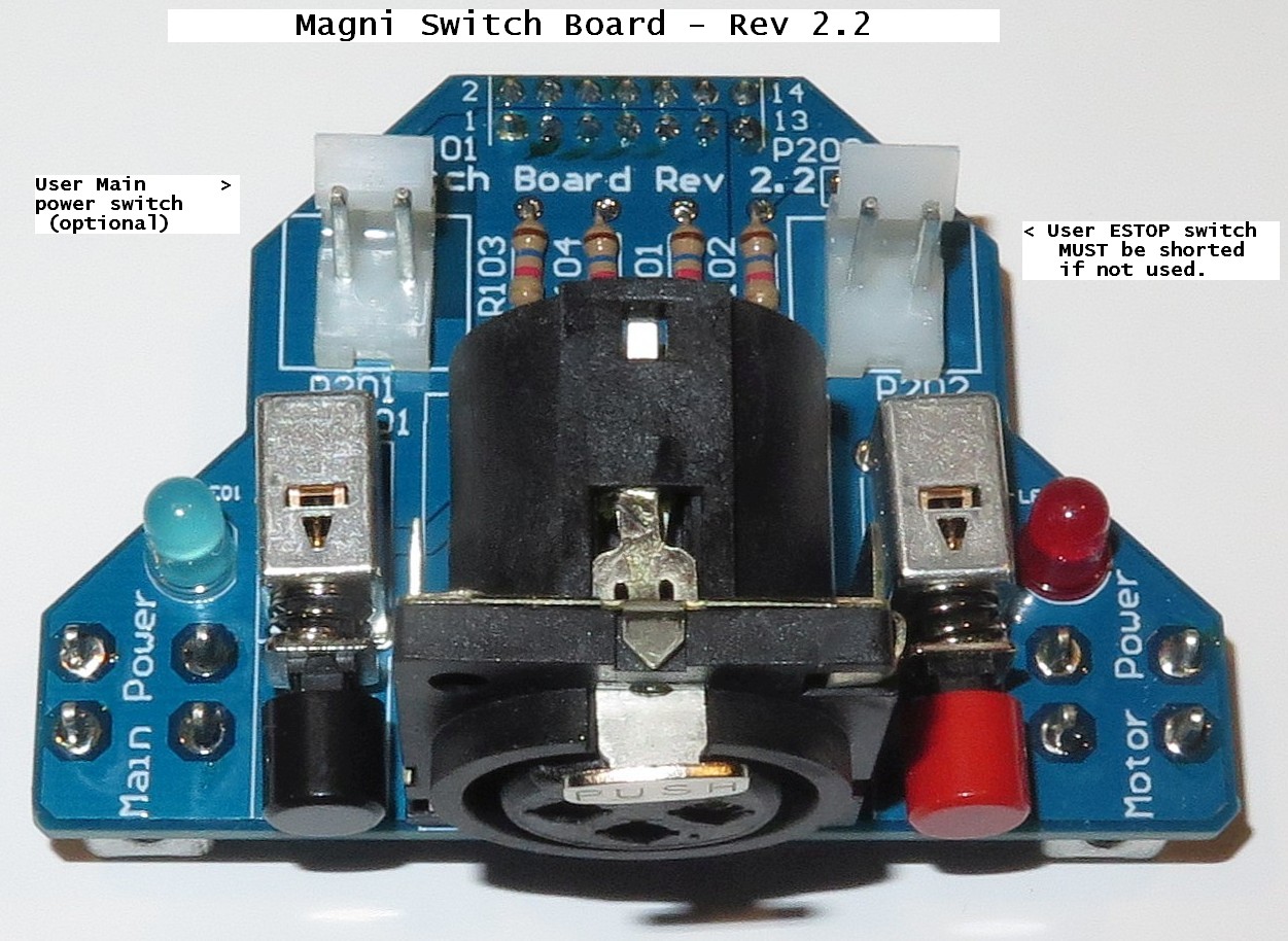
The revision 2.2 board has P202 seen in the back right that is wired in series with the red keycap ESTOP switch on the board. Our plan is we will ship the connector that mates with P202 that has one piece of wire sorted to itself. In this way P202 is shorted from the factory and a user may remove this jack and put two wires going to his own ESTOP switch for his own robot needs.
However it is done P202 MUST be connected or no motor power will be enabled
On the back left you see P201 which is wired in parallel with the black main power switch. The thought here is users who want a remote main power switch connect a connector to two wires and then leave the installed main power switch OFF or pushed in. The customer switch will then be the power switch.
For either ESTOP switch or Main Power switch we ship one jumper that can be modified but sometimes for replacment boards you may want the part numbers for the cable. Ideally a crimp tool would be used for the pins but it is possible to manually solder onto pins although that is time consuming and a little tricky to wrap the crimp metal around the wire so the pin will fit in the housing.
Plastic Housing:  Molex 0009501021.  Digi-Key Part Num WM18813-ND
Female Pins:      Molex 0008701031.  Digi-Key part Num WM18820CT-ND
Switch Boards To Support Rev 5.x MCB Boards
-
The main thing to watch for is if the board has 3 resistors it is old for rev 4.9 or earlier MCB boards.
-
A REV 5.x MCB REQUIRES A 4 RESISTOR DESIGN AND BE LABELED REV 2.x or later.
-
A rev 2.x switch board with 4 resistors can be used with earlier MCB boards.
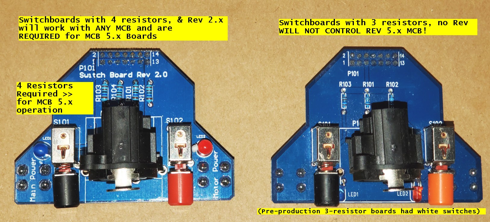
Very early pre-production Switch boards
In early prototypes there were switch boards with large white switches that had green leds in them to show the state. These should not be in production units unless some sort of replacement had to happen early in first production units.
Removal And Replacement Of Magni Main PC Boards
The firmware on the MCB is critical to have up to date to avoid prior bugs from showing up when a different MCB is put in the robot. The MCB board may be shipped with old firmware so all replacements of the MCB should be followed by checking and updating MCB firmware after the replacement board is running. Refer to Upgrading MCB Firmware to check and upgrade if needed.
YOU MUST REMOVE POWER CABLES FROM THE BATTERIES FOR THESE PROCEDURES BECAUSE WE MUST BE SURE THE FULL BATTERY VOLTAGE IS NOT PRESENT ON THE BOARD WHEN REPLACED.
Removal Of Main Control Board (MCB)
These steps are taken to remove the main board. It should be noted that to replace a board these steps can be done in reverse order.
- Disconnect ALL battery leads from your batteries. We always leave the thick red and black power cables connected to the MCB board because if you get a replacement it will have the power cables attached. The cables are routed in a very specific way with the mounting hardware also done in a precise way thus we do not remove these cables.
- Disconnect both large multi-pin black wheel cables with inline jacks from the wheels. These can be very tight so you may need a very good grip and work the connectors gently back and forth as you try to extract. Be careful to not bang your knuckles as they can release all at once. See the ‘the motor cables to the wheels’ section of unboxing for pictures
-
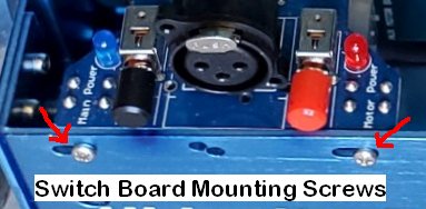
Unscrew the 2 screws that hold the small ‘Switch Board’ to the Magni front panel and place the screws in a safe place. After screw removal the switch board can be unplugged from the main MCB board and taken out then set aside perhaps near the 2 screws.
- If your Magni has the sonar board you should remove it’s 50 pin cable from the main MCB board and remove the sonar board to make things easier for this process. You can see how it is installed and do the reverse that is described on the last half of the sonar sensors page
- We are going to free up the RaspiCam flat white cable so the Raspberry Pi can be removed easier in next step. Refer to camera sensors for pictures. Locate the white flat thin ribbon cable to the camera at the point it gets to the camera. Take note at this time that the blue tape on the flat cable is away from the RaspiCam PCB which will have to happen as you reassemble later. NOTE: The jack for the cable is very delicate so just pull back the tabs on each side just a mm or two and do not force it harder or it may break the tabs. Pull out the cable from the camera end.
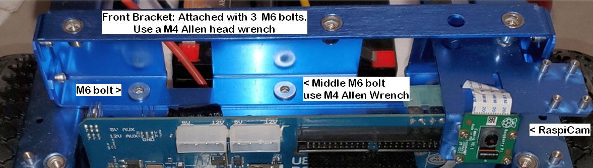
- Remove the large sheetmetal rectangular Front Bracket that has the raspicam camera bracket riveted to it. Refer to the middle of unboxing and see the
Front Bracketpicture. The removal is done using a long allen wrench with 4mm tip for the bolts that hold this 24mm wide side to side bar to the top shelf of the Magni chassis. The 4mm allen wrench has to be long enough to go through from the top of the bar all the way to insert into the bolts.
- Unscrew one phillips head screw that may be holding your raspberry Pi to a 20mm tall standoff near the center of the MCB. Save this and take note of the washers and 1mm thick plastic spacers on some boards and don’t loose these tiny parts.
- Now you may gently ease out the Raspberry Pi. This is a bit tricky so take your time. Care should be taken to never apply any pressure to the very thin Micro SD card in this process as it is easy to break. You first back the Pi out of the 40 pin tall connector. Next you have to remove in an upward direction the Raspberry Pi clear of the chassis. Place the Raspberry Pi aside in your work area. I find that gentle rocking away and towards the MCB at the side of the 20mm standoff while pulling pins out is easiest.
- Now it is time to unscrew the 4 M3 button head screws that hold the MCB to the chassis using a 2mm long Allen wrench that came with the robot or your own. For some of the screws you may need to run a long allen wrench through access holes in the chassis 5cm away in some cases to get the allen driver straight into the screw head. Watch where these screws go and don’t loose them.
- Getting the MCB board out requires patience and care. Do not force anything and do not rub any parts off from contact with the sheet metal on the way out! It will be removed after no screws hold it by working it out upward now that the front bracket is removed. As you look behind the MCB in the battery area free up the thick black cables and/or thick power cables then work the MCB out a bit more and eventually it will be guided out in an upward direction. Just take your time and always watch for any parts that may get bent or scraped so try to do this carefully and take your time.
- Once the MCB board is out we leave on the thick red and black cables and return those with the MCB if you have been requested to return the board for us to study the failure.
This completes the mechanical replacement of the MCB
🔧 USB and the Other Connectors On The Raspberry Pi Computer
Although not technically on the MCB itself these can be extremely popular for many users. The Ethernet can be very handy for lab development to not have to worry about WiFi or lack of WiFi.
One common use is that users can add more serial ports using USB to serial ports. Another common usage is to plug into a USB port for a device such as a Lidar or other expansion IO device. Keep in mind the power supplied by USB ports varies and in a general way may be lower than your device requires so see the power jacks we discuss next rather than expect the USB to supply currents much over 100mA in a reliable way.
Raspberry Pi Audio And Display connectors
The Raspberry Pi may be connected to two types of full displays.
We sometimes use the Raspberry Pi 7” touch screen that plugs into the flat ribbon cable on one edge of this small CPU. You will very soon see some Magni based products using this display.
There is an HDMI connector on the Raspberry Pi 3 and the recent shipments we have use the Raspberry Pi 4 which has two HDMI micro connectors.
All models of the Raspberry Pi have audio input and output on a 3.5mm compound jack.
🔧 PC Style Power Connectors with 5V and 12V
The picture below shows the 4 power supplies available from connectors or holes near the top of the board. These can be of use for cases where a user may need 12V or 5V for their own circuits.
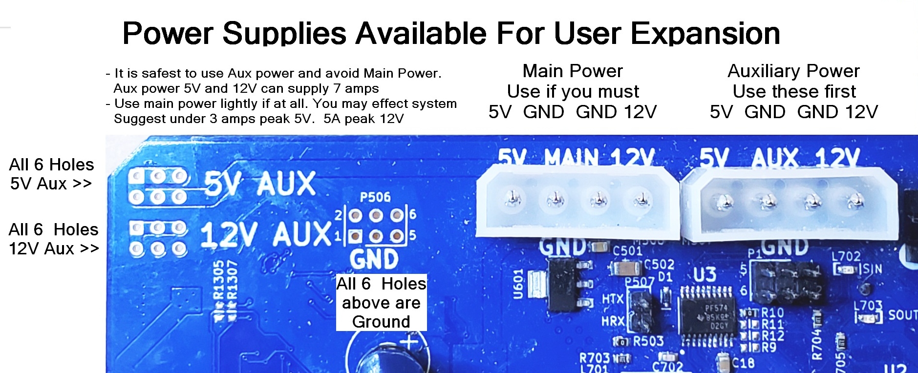
We prefer that the user use the Auxilary 12V and 5V power first because they are separate from the robot main supplies. The auxilary supplies should be able to supply 12V at 7 amps and 5V at 7 amps. High transient loads may cause them to briefly sag.
There are other places to solder to the Aux power connections seen in this picture to the left of the large white PC style power connectors.
To make your own cables here are the mating connector housing and pin numbers
- Housing is
Molex 0015244048(Available as Digikey # WM6982-ND) - Crimp pins are
Molex 0002081201(Available as DigiKey # WM2293CT-ND)
As the silkscreen shows for both of these connectors 5V is on the left then the two centeral pins are ground and on the right is 12V. These are accurate, regulated supplies.
Power Connectors On Bottom Of The Board
There are two power only expansion connectors near the bottom of the board by the large automotive main Fuse. These can easily supply power for most 5V usb powered devices. Each connector is rated at 1.5amp max and they are both to the 5V Aux power which can supply about 4-5amp total for typical loads given that many loads can have higher current spikes in the device in use. Keep in mind that many USB cables have very small gauge wires so evaluate the voltage at the far end of the cable and keep your cables short as possible.
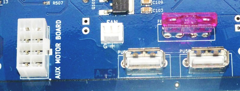
The USB Style 5V Power
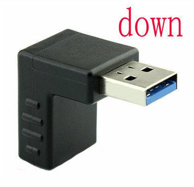
Located at the bottom of the MCB board as the board is in the Magni robot there are two 5V connectors that you may plug in a standard USB A cable to get 5V. There is no USB data at all, just power. If you need full USB connectors you need to plug into up to 4 USB jacks on the Raspberry Pi computer attached to the MCB.
If your USB power cables cannot plug into these jacks we recommend you get some right angle USB 3.0 adapters. Note that you need the type where the plastic in the adapter is going to fit into our connectors thus the plastic must be above the hole for the part that plugs in. This type is normally called ‘Down’ although it will point up in our case for the MCB. Here is some search text to find the jack we recommend but there are other vendors. USB 3.0 Adapter 90 Degree Male to Female Combo Vertical Up and Down Angle Coupler Connector
The 12V Fan Power Connector
Starting with MCB rev 5.2 we have added a standard 3-pin 12V Fan Power Jack where Ground is the left pin with ‘G’ and 12V is on the center pin. It is 3-pins so 12V can be in the middle to avoid polarity issues.
This is a Molex 22232031 connector so to make cables these parts apply
- Housing is
Molex 0022013037(Available as DigiKey # 900-0022013037-ND) - Crimp pins are
Molex 0008500113(Available as Digikey # WM1114CT-ND)
The AUX MOTOR BOARD High Voltage Connectors
The 8-pin Aux Motor Board jack allows for high current full unregulated battery voltage usage. We recommend you contact us if you wish to use this jack. The jack was put on this board for an expansion jack for internal. See the P1001 jack description in the To see this comprehensive document please see Motor Controller Board Pinouts
Main Battery Fuse
The 35Amp main battery fuse is just above the USB power jacks and supplies protection for the system. It can be a different color. For almost ALL our customers this fuse really could be 10 or 15 amps so you may wish to use a lower current fuse for added safety especially if you are going to be changing around boards and so on frequently.
We do see customers drop things on the still plugged in electronics (WHICH WE TRY TO WARN THEM NOT TO DO) and a 35 amp fuse can lead to great damage. For most all our customers this fuse does not have to be over 15 amps.
Master Control Board Led Indicators
Although the LED indicators are discussed in assorted sections of this document a brief listing of them here was felt to be of value as a summary.
Power Supply And MCB Status LED
A row of 5 leds can be seen to the lower left as you look at the MCB board. In boards prior to rev 5.0 they were vertical but as of rev 5.0 and later they have been horizontal. Here is a table showing the meaning of these leds from left to right.
The 4 power supply leds should always be on when power is active. The 12V Main and 5V Main are critical for robot operation. Auxiliary supplies are for user only.
| Led Name | Description |
|---|---|
| 12VA | Lights when the 12V Auxiliary supply is active |
| 12VM | Lights when the 12V Main supply is active |
| 5VM | Lights when the 5V Main supply is active |
| 5VA | Lights when the 5V Auxiliary supply is active |
| STAT | Shows status for the MCB onboard processor |
The STAT led is more recently labeled STATUS and is highlighted and is the most complex led. Normally it is on with very brief drop-outs every 4 to 6 seconds. The exact period of the dropouts indicates firmware version and is explained on firmware version page. As of firmware v37 we have had a self test and battery monitoring function where the STATUS led if it shows odd blink patterns is indicating some form of warning or battery low indication. See the ‘Verification’ page for details on the blink codes.
The Main Power and Motor Power Active Leds
Starting with MCB version 5.0 there exists leds on the MCB board that indicate when either or both of the two main power feeds is active on the MCB.
When the main power is active there is an led on the far left and lower part of the board that will be on. This indicates the main power is active and the board is powered up. If this is on but the black power button is off there may be a problem with our ECB, Electronic Circuit Breaker circuit.
When main power is active AND the red ‘ESTOP switch is also in the out position the motor power led located on the far right and very low on the MCB will be on. If this LED is stuck on and does not turn off it indicates a problem with the Motor power ECB, Electronic Circuit Breaker circuit.
The 3.3V Onboard Power Regulator
Starting with MCB version 5.2 we have an onboard 3.3V power regulator so that the 3.3V circuits do not have to use the 3.3V power from the Raspberry Pi. This is both a reliability enhancement as well as a way to have more 3.3V power even when a user uses a different CPU than the Raspberry Pi. We do not directly support usage of this supply for user circuits yet.
There is an led that should be on whenever the board is powered up and that led is labeled 3.3V and is located about 2cm lower than the large white Main Power jack at the top of the board.
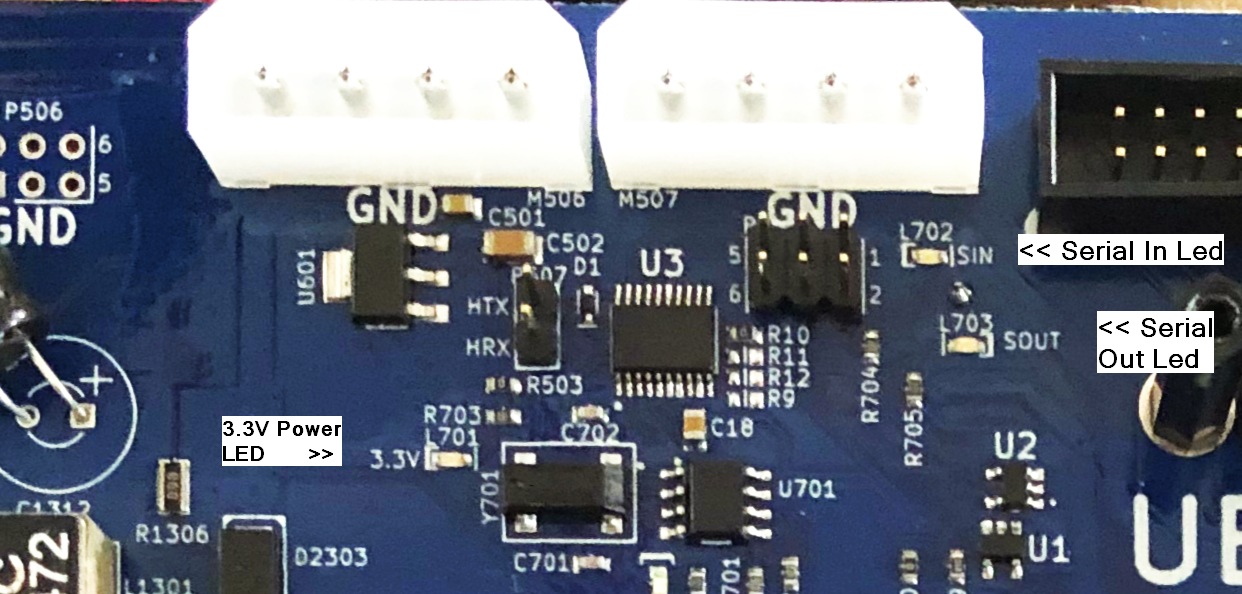
The Serial Communication indicators
Starting with version 5.2 of the MCB board we added two leds that normally blink very fast once the system has come up and is running.
These two leds are labeled SIN and SOUT and are located just below the right large white AUX power connector at the very top of the board near the center.
Normally the SOUT led will blink very fast right after power up of the robot. The SIN led will take a minute or more to blink because the Raspberry Pi has to initialize the Linux operating system before it gets to starting to communicate with the MCB. Unfortunately the led is a bit hard to see but be aware that until this SIN led starts to blink very fast the robot will not respond to any sort of command. So the leds is valuable to tell when the robot is ready to go.
I2C Expansion Jack Used For OLED display
We are starting in 2022 to ship a small OLED display with each MCB. The OLED display is driven by a ROS node and is connected to the I2C bus of the Raspberry Pi.
Starting with MCB rev 5.2 we have had a 4-pin 0.1” pin spacing female jack that brings out the Raspberry Pi I2C lines as well as the MCB onboard 3.3V power. Rev 5.1 board also had this jack but because power for 3.3 came from the Raspberry Pi we do not recommend using that jack for the OLED display.
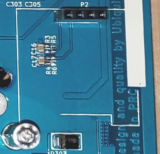
From left to right here are the P2 I2C expansion jack pin definitions
| Pin | Description |
|---|---|
| GND | Ground for the power and I2C |
| 3V3 | This is 3.3V power some boards call Vcc |
| SCL | The I2C Clock Line. No need to add more pullups |
| SDA | The I2C Data Line. No need to add more pullups |
🔧 Expansion Boards For IO and IMU Capabilities
We are working on small I2C based expansion board designs to be available in 2022 that will plug into the MCB board and still allow the OLED display to then plug in on top of that board to form a stack of boards powered by the MCB P2 jack.
The first board will have a BNO055 IMU as well as 8 bits of digital IO to drive 3 on-board LEDs as well as offer 5 lines for low current digital output or inputs at 3.3V digital levels.
Another board is only in low volume 1st prototype form that would offer more IO at higher currents some with relay driver ability. This board also would have 4 0-3V analog ADC inputs as well as 2 0-3V DAC outputs both of which are meant for only slow or static analog signal usage. It would have 2 switches and some leds and an expansion I2C jack for ease of customer I2C connections.
🔧 Making A Remote RF Estop switch
Starting with our SwitchBoard rev 2.2 it is now possible to include either your own ESTOP switch on your chassis cover or shell. Besides that though here we describe using low cost RF control units that offer a latched set of relay connections so you can install an RF safety switch to turn off Magni Power remotely if you require that for your own safety needs.
I suggest one particular RF control unit that by adding a connector for 12V power and a connector to plug into our Switch board jack called P202 you can have such an RF controlled power switch. Note that this could also be done on our rev 2.2 switch board to have the main power-on also with RF if you wish that feature.
We find the one that looks like this picture and has a dual button control unit allows for latched or momentary power modes. You can find this style on EBay using the search string of DC12V 1CH Relay Receiver RF Transmitter Remote Control Switch
You must find a control that will latch on and stay on until you push a button on the control later. Once installed you keep it enabled till you must stop for safety and then one click will stop the unit. Many of these have programming ability but with really bad directions.
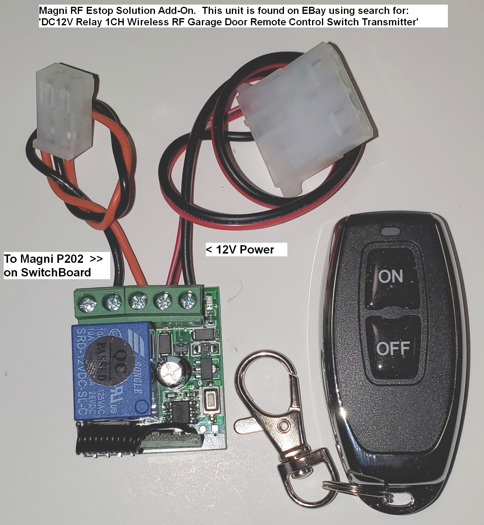
This remote RF relay comes with black plastic box that latches closed firmly and covers the circuit board without taking much space. The case is not shown in this picture simply to show the power and switch wire connections. You could use good quality double sided flexible tape to attach this to the inside space near the switch board or make a bracket if you are going to ship this with your product.
Here are some details to help make cables for this sort of unit.
Here is the connector for the ESTOP that goes to P202 but note that we ship this connector and a wire that loops to short this connection with each current Magni robot. You can then cut that existing wire and splice longer 2 wires back to the RF switch unit. Never leave exposed connections from spliced wires so cover them with shrink wrap or electrical tape of course.
Plastic Housing:  Molex 0009501021.  Digi-Key Part Num WM18813-ND
Female Pins:      Molex 0008701031.  Digi-Key part Num WM18820CT-ND
Here is the connector for the 12V power to supply it from MCB AUX power jack that is also described in detail earlier in this page. We use a very standard connector that had popular usage as the older disk drive power connectors some years back. If you have an older PC power supply sitting about you could use the yellow and black wires on one of it’s cables that was meant to go to a disk drive after cutting the cable off of the old power supply. If no such ‘junk’ about then here are connector details.
Plastic Housing:  Molex 0015244048   Digi-Key Part Num WM6982-ND
Female Pins:      Molex 0002081201   Digi-Key Part NumWM2293CT-ND
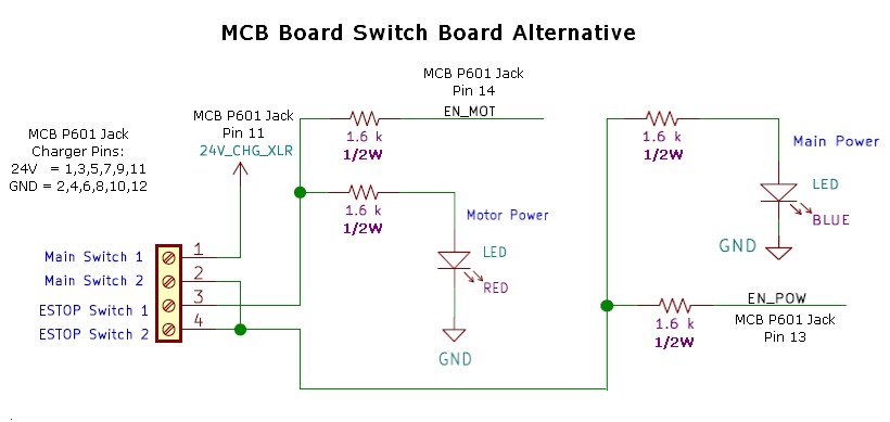
Alternative Wiring To Replace Our Switch Board
Some users mount the MCB in their chassis and do not want to use the Switch Board that we normally use for stock Magni units. Recent switch boards have jacks to allow users to have remote power and ESTOP switches but some users want to avoid use of the switch board for mechanical reasons in their own product.
Below is the wiring you would have to supply to the MCB 14-pin P601 jack. You MUST use 1/2 watt resistors as shown. The switches themselves are low current and will only need to control under an amp of current at 30V
Be very careful if you use a ribbon cable or other wiring because that connector has direct battery access and EXTREME currents are possible. Thus Measure and verify and measure AGAIN before going ‘live’ with direct battery connect. I have indicated off to the left the pins used for the battery charger because you would also not have the XLR jack for charger without our Switch Board.