Route Setup
To set up a route you’ll first have to place fiducial markers in desired locations, and then use the touchscreen to set up which turn markers each robot should follow.
How to place floor markers
To make sure your setup works as intended, a set of rules need to be followed to prevent undesired behaviour:
-
Each marker should accurately point towards the next one
-
Before sticking markers to the ground using their strong adhesive back side, it is recommended to stick them to the ground using some tape, so that you can test if your route setup is correct. Be careful that you don’t cover the inner black part of the marker with the tape. After you’ve made sure the route is setup correctly, you can stick the markers by removing their back side. Stick the markers onto clean, smooth floor.
-
Route loops should be set up in a way that makes the robots turn only left or right depending on where the lidar is mounted. This is done to prevent blind spot collisions and to simplify robot to robot interactions.
-
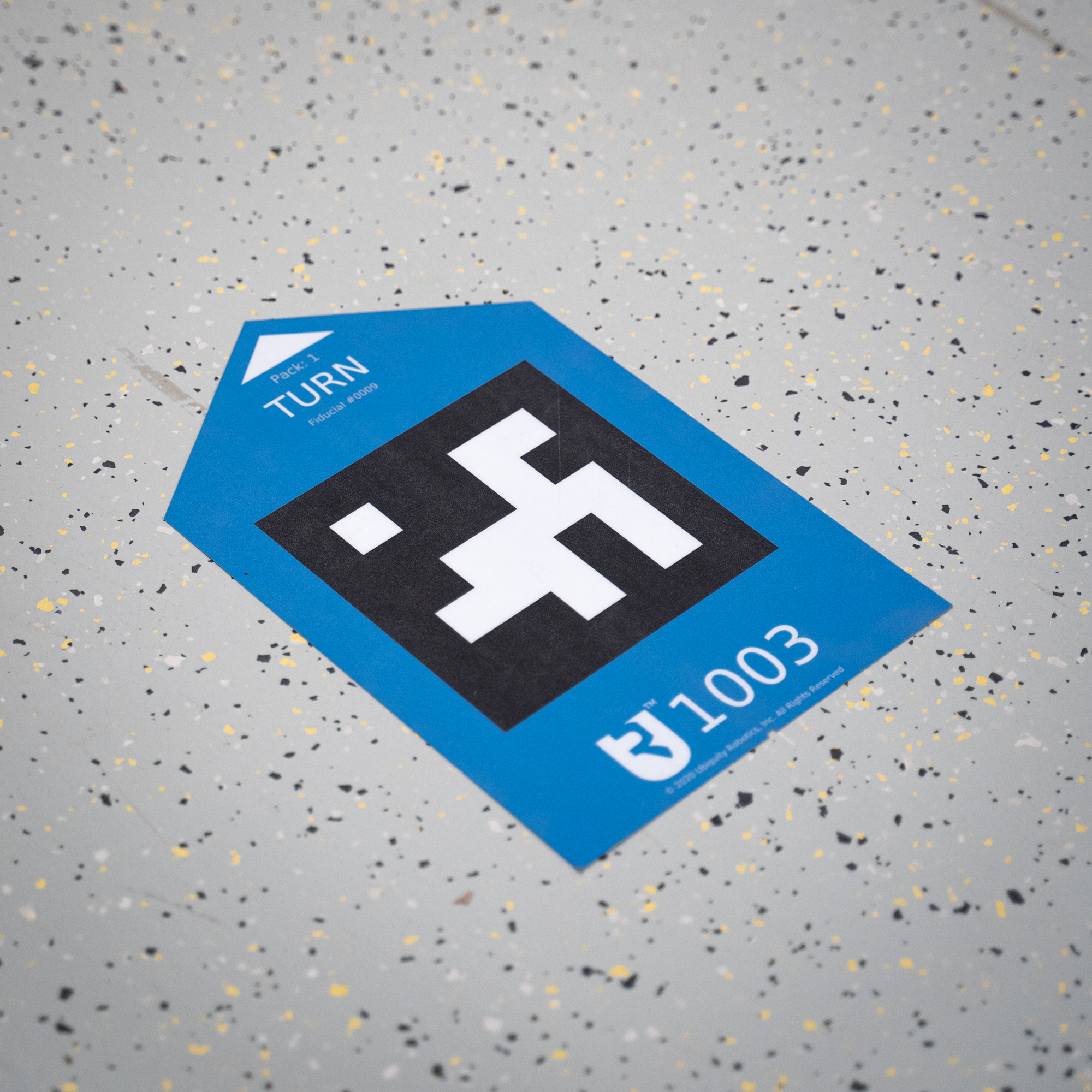 TURN markers should be used to create crossroads (or switches, in railroad terms)
 -
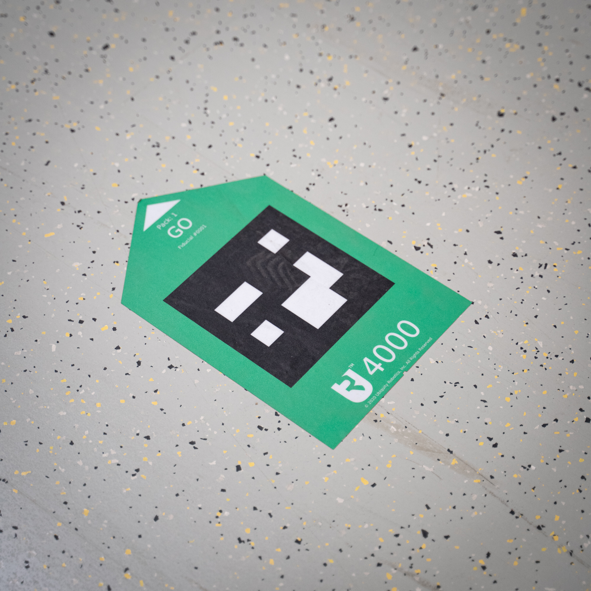 GO markers should be used for one-way routes, where robot can drive only towards the next marker.
 -
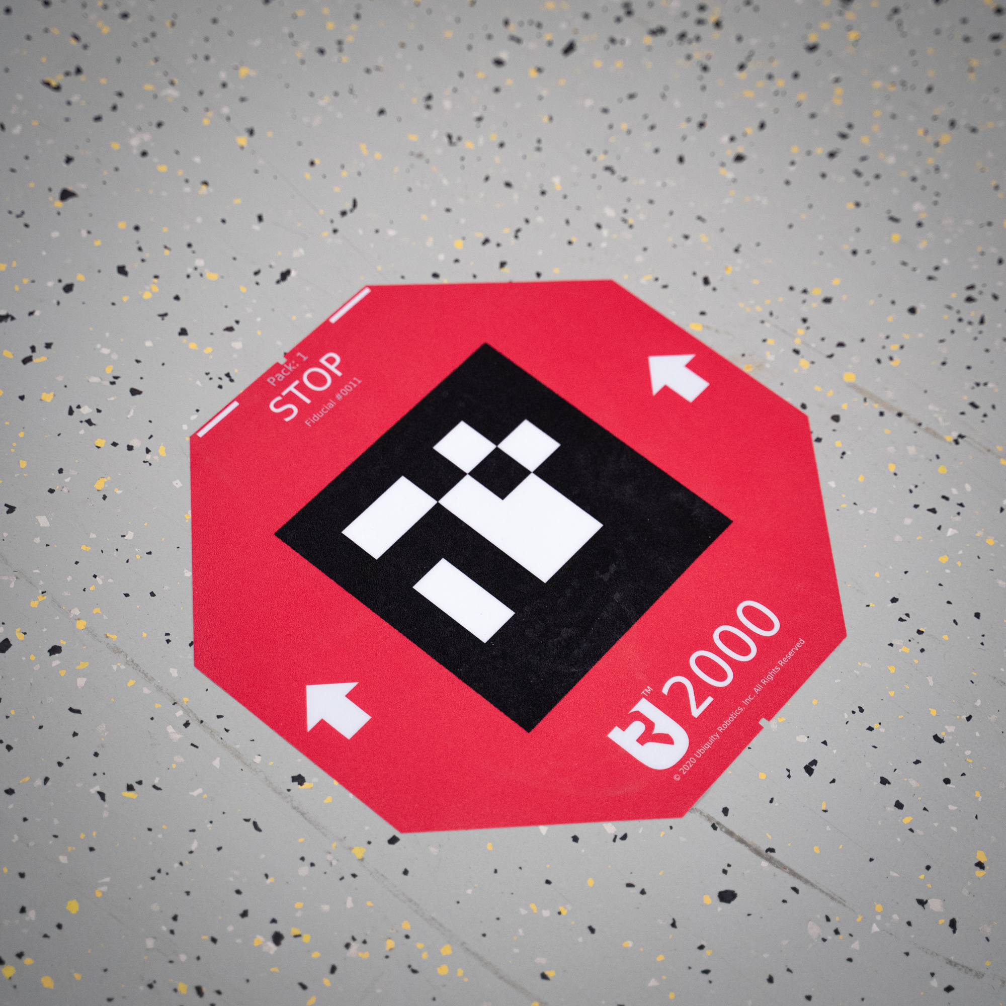 STOP markers will make the robot stop and turn to continue, so make sure it’s possible to continue the route in the direction of the arrow.
 -
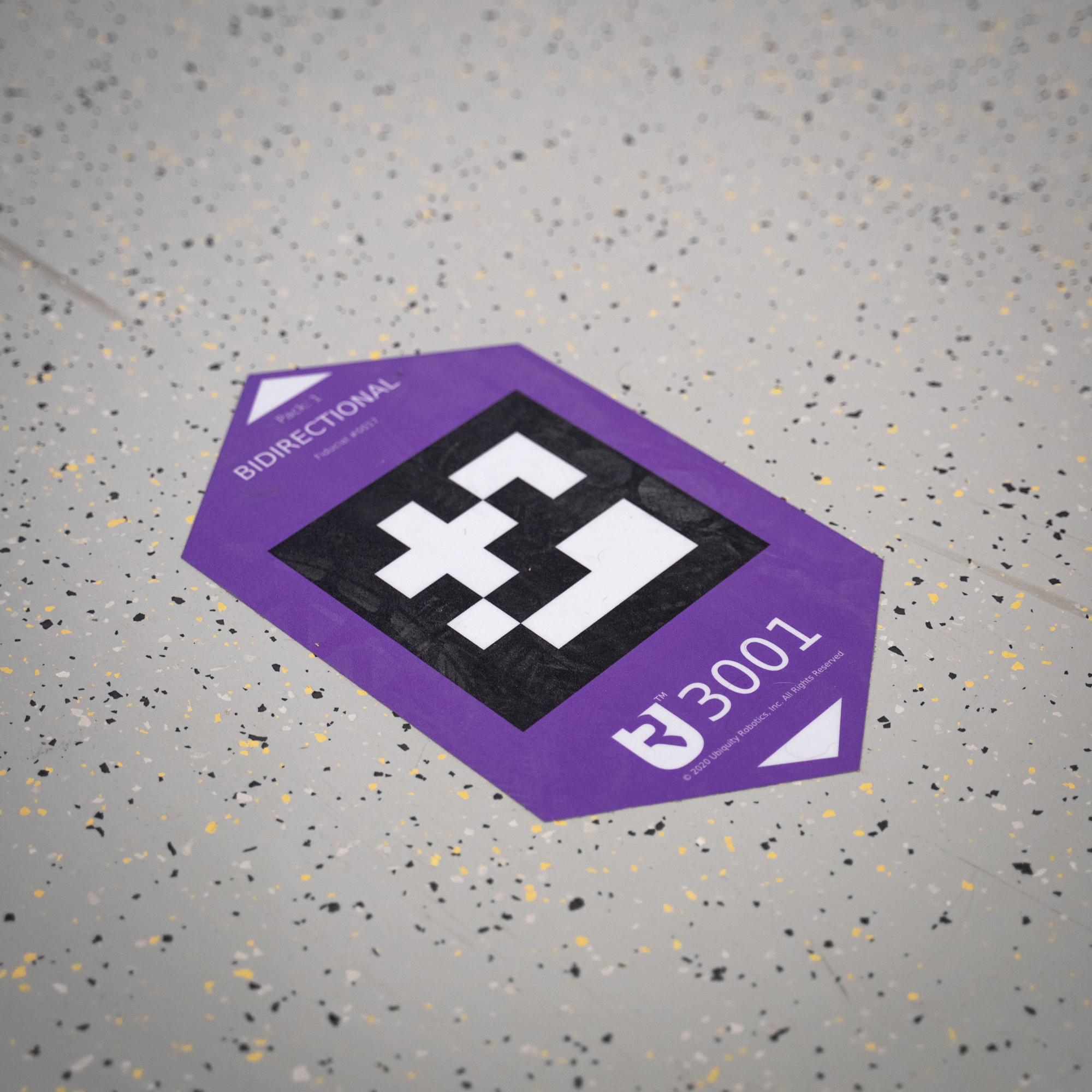 BIDIRECTIONAL markers should be used for two-way routes, where the robot can drive in both directions while driving straight (e.g. to and from a contact charger). The robot should never approach the BIDIRECTIONAL markers from the side, since it’s not clear which way it should turn. If you expect to have more than one robot on a route, you should have a seperate outbound and return path otherwise robots may meet head to head, which will cause both robots to stop. BIDIRECTIONAL markers should only be used on branches where you expect only one robot to be present in that branch at a time.
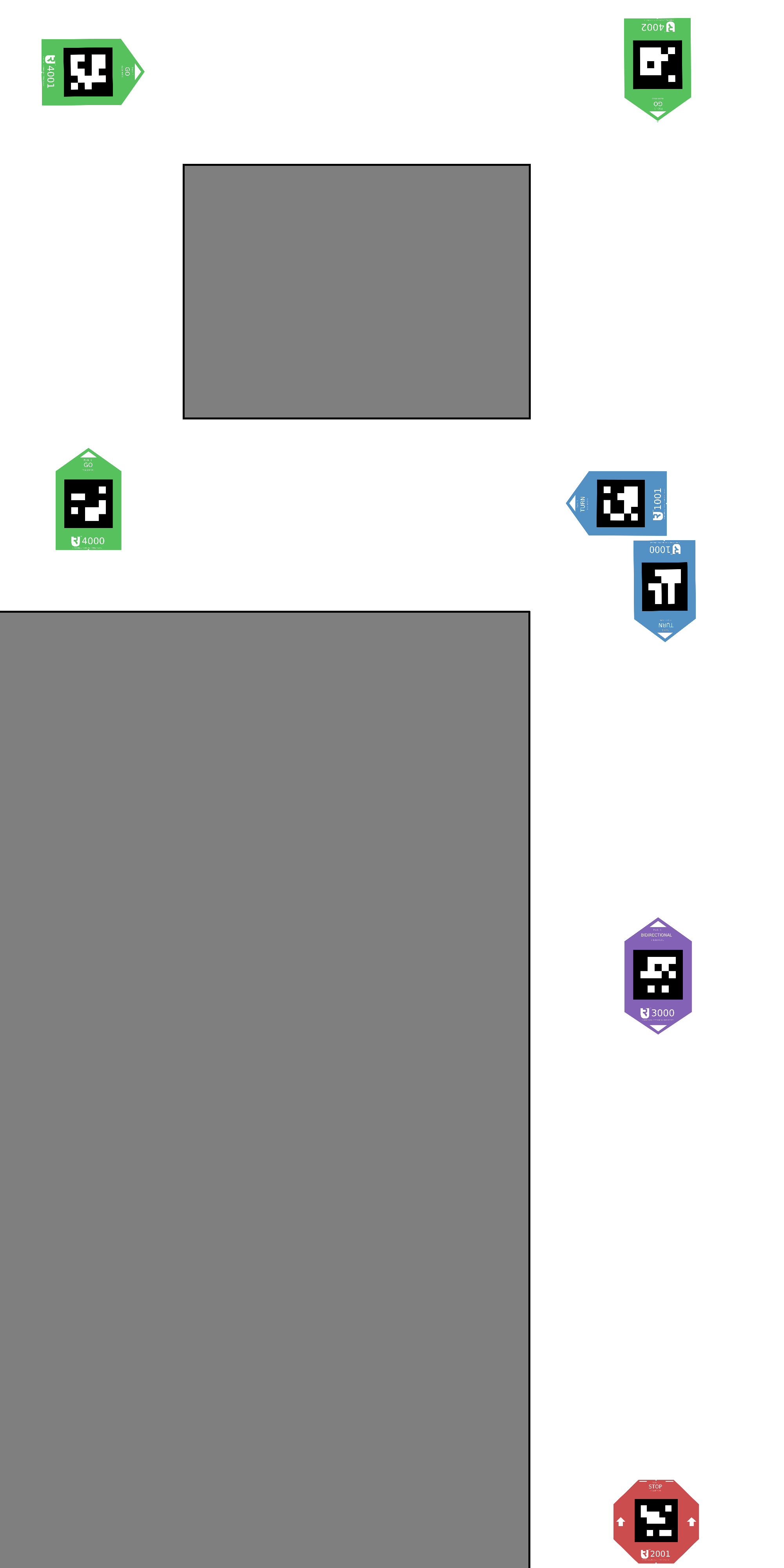
An example of a simple marker layout is shown in the figure below.
Ignored opposite markers
By default, the GO markers which are rotated in the opposite direction as the robot is driving are ignored. This is so that the outbound path and return paths work correctly when inbound and outbound paths are close together (refer to the next section). Otherwise, if the robot is driving on the inbound path, it might detect and follow the opposing markers from the outbound path.
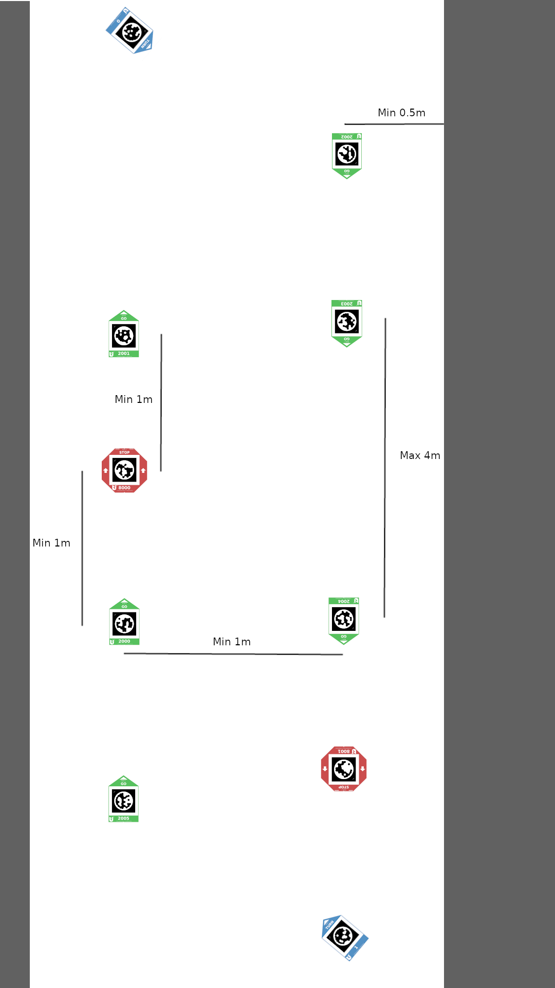
Circuit route
If you want multiple robots to drive on the same marker setup, you should arrange the markers in a so-called “Circuit route”, so that the robots won’t collide into each other. This type of marker setup is recommended even if you have only one robot, because you never know when you will add another robot to your fleet. We divide circuit route into an inbound and an outbound path. Inbound serves as the path for robots to drive to the goal and the outbound is the path which is used for the robots to return back to the starting point. The inbound and outbound paths should be at a little more (about 20 cm more) than 1 robot width apart, so that the robots can pass each other without collision. If you have space, its convienient to place the routes 1 meter apart. On both ends of the path, markers should be arranged in a specific way, shown in the image bellow. When setting up a route, the measurements from the image bellow need to be considered. If you want to include a STOP marker into the Circuit route, the best way of placing it is one meter behind the GO marker. GO markers must be max 4-5 meters apart regardless of where you put the STOP markers, because the STOP markers are ignored in the case if you don’t want the robot to stop on them. As seen from the image, on each end of the Circuit route, there is a TURN marker, which you need to include into the route on the touchscreen. This can’t be a GO marker, because it would be ignored as it is turned in opposite direction as the robot’s driving direction.
Branches from main circuit route
You can also do “branches” from the main circular route similarly as shown on the image bellow.
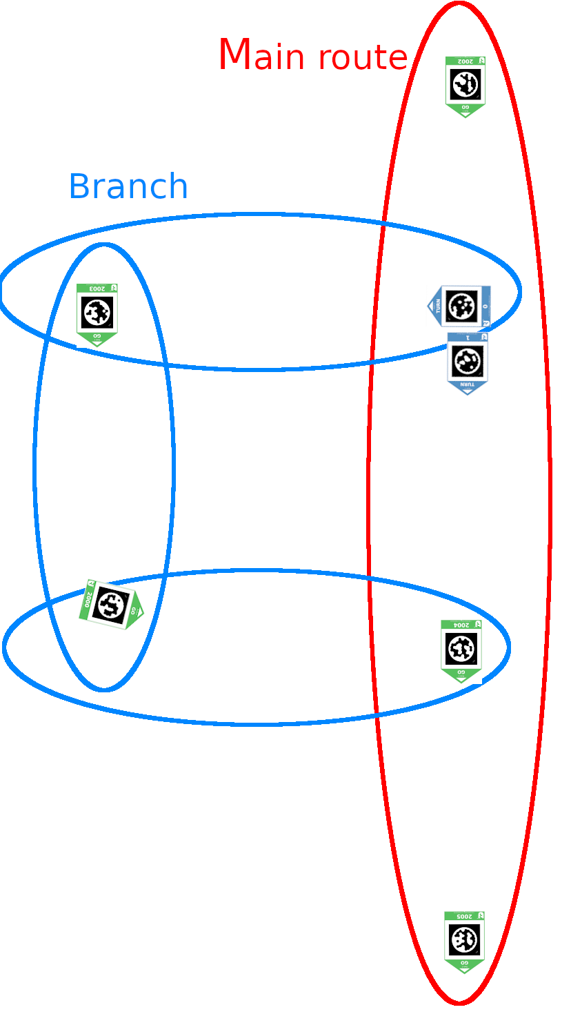
As you can see, there is a possibility that two robots would collide into each other on the marker where the branch merges back into the main route. This is handeled in a way that the robot comming from the branch always “looks” to the left with LIDAR in order to see if there is another robot approaching from the main route. If this is the case, the robot approaching from the branch will stop and wait for the robot on the main route to pass.
But this introduces a problem. The robots always look to the left when turning right on a marker in order to detect a potential robot on the main route. This means that if the robot is just turning right (and it is not going back to the main route), ideally there should also be about two meters of clearance on the left side of the robot so that the wall or any other obstacle is not detected as the robot approaching from the main route. So, if the robot is driving in a hallway which is turning right, you should put the inbound path as close to the right wall as needed so that there is still 2 meters of clearance on the left side of the robot. Or, if that’s not possible, you should disable t collision detection for each individual marker, that makes the robot turn right, on which you don’t want the robot to stop because of the obstacle on the left. This can be done on the touchscreen’s route settings screen. By clicking on any marker in the route, a popup will open where you can check the “Disable T collision check” checkbox. Bear in mind that to rejoin the main route at the point where the main route makes a 90 degree turn will create problems with this collision avoidance. Please rejoin the main route a few cm earlier than where the main route takes a 90 degree turn.
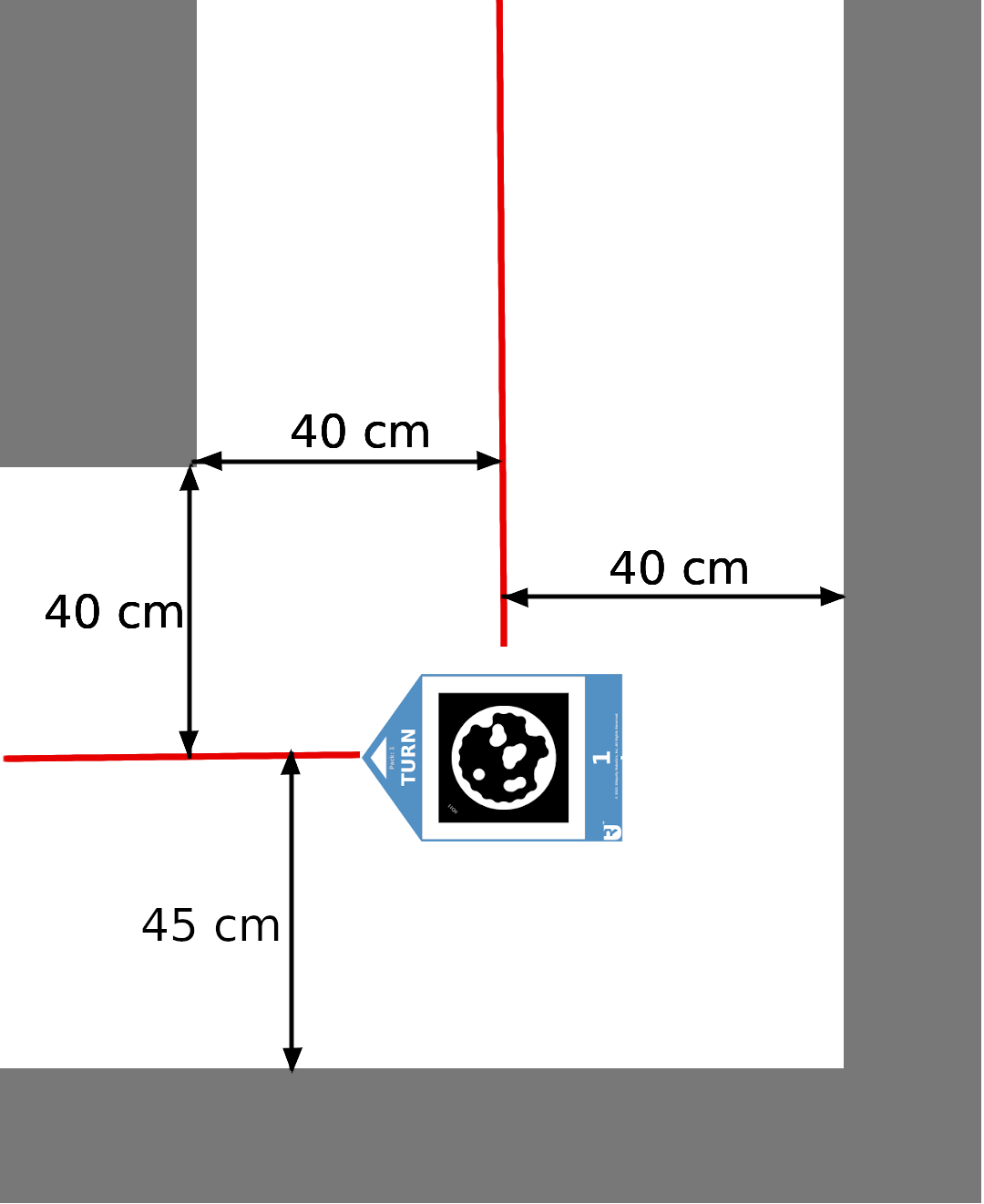
Narrow hallway limitations
There are some minimum distances from the route to walls which are presented on the image bellow.
Touchscreen UI
In this section we will present the web application made for the 7’’ touchscreen monitor. Its main functionality is to manage routes for ConveyorBot. On the top of all screens, there is a menu bar, which offers functionalities like rebooting the robot, monitoring battery percentage, navigating to “Control panel screen”, etc. On the top right corner of the “Control panel screen”, there is a map icon which leads to “Route settings screen”. On that screen, the routes can be set up.
Control panel screen
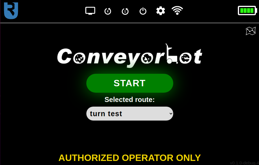
The most noticeable part of the “Control panel screen” is the big green “Start/Stop button”, with “START” written on it. After pressing it, it changes its color to red and its text to “STOP”. It is used for the robot to start or stop following the markers of the currently selected route. When the robot finishes the route by stopping on a STOP marker, this button changes its color to blue and its text to “CONTINUE”. Now, when pressing this button, the robot will start following the route again from its beginning.
The route can be easily selected in the dropdown menu, which is located below the “Start/Stop button”. To edit, create or delete a route, the gear icon in the top right corner can be pressed, which leads to the “Settings screen”. If you want to reset the route (to start the route from the beginning), you should select another route and then the desired route again (currently there is no “reset route” button).
The Control panel screen with route “turn test” selected is shown on the image below.
Menu bar
The menu bar is present on the top of all screens. On its left side, there is a Ubiquity Robotics’ logo, which is actually a button that always leads to the “Control panel screen”. On the right side of the menu bar, there is a battery level indicator. When the battery goes under 40%, a low battery popup will be shown. When this happens, you should stop using the robot and start charging it. In the middle, there are several buttons, each having its own functionality. The first one (from left to right), shaped as a computer monitor, leads to the “Debug screen”, on which the user can monitor the camera’s image stream and detected markers or move the robot with the software joystick. The second button, shaped as a letter “R” in a circular arrow, prompts the user to reboot the robot. The third button, shaped as the letter “S” in a circular arrow, prompts the user to reboot the robot’s software. This is useful, because it functions in a similar way as rebooting the robot, but is faster than it. The fourth button, shaped as an on/off symbol, prompts the user to turn off the robot. The fifth button, shaped as a sprocket, leads the user to the “Debug settings” screen. On this screen there are additional settings for updating and recording ROS’ topics into a “bag file”. This is used for debugging purposes. The sixth button is a WiFi state indicator. If the robot is connected to the WiFi, this button has a regular WiFi icon shape, indicating the WiFi strength. If the WiFi is disconnected, it has the same shape, but with a cross symbol drawn over it. If the WiFi is in the hotspot mode, it has a shape of two regular WiFi icons rotated by 90° to left and right. Pressing on this icon displays the WiFi info, which is the IP address, SSID and the hostname. Here you can also connect to a new WiFi access point by entering the SSID and password into appropriate fields and clicking on “Connect to the new WiFi” button.
Route settings screen
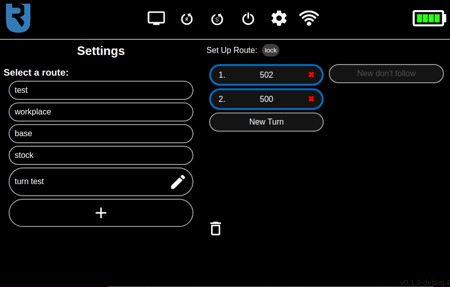
On the left side of this screen, there is a route selection part. To add a new route, the “+” shaped button below all routes can be pressed. When clicking on any of the routes displayed here, the route editor will be displayed on the right side of the screen, where you can edit the selected route.
The route editor has two columns. In the left one, the markers to follow can be specified and on the right part, the markers to ignore can be specified. The specified markers can also be rearranged by dragging and dropping them. The drag and drop functionality can be disabled, so that the list of markers can be scrolled up and down, without accidentally rearranging the markers. This can be done by clicking on the “lock/unlock” button above the left column. The function of “markers to follow” and “markers to ignore” and instructions on how to correctly set up a route will be described in the next section.
To delete the route, which is currently being edited, click on the button with the bin icon on the bottom of the screen.
The settings screen is shown on the image below.
Route management
The route management functionality allows ConveyorBot robot to navigate itself in a more advanced manner. If you press the route settings button on the Control Panel screen, you’ll see the main route management page. This was described already in the previous section of this page.
Now we will tell you how to properly set up a route. An analogy for how the route setup works is the way somebody navigates you while driving a car. The navigator only tells you where you have to turn in the crossroads - he doesn’t tell you that you have to go straight on a road which is itself straight (and has no other ways to turn), or to stop where there is already a stop sign. So, to set up a route on which the robot will drive, you have to specify only the sequence of TURN markers in the crossroads of the route. Actually, all other TURN markers (the ones which are not specified in the route plan) are ignored by default. You don’t have to specify GO, STOP or BIDIR markers (but you have to do this in a special case, specified later in this section).
To specify the order of turns in crossroads, put the numbers of TURN markers, which mark the appropriate turns, into the left column of the route editor in the correct order.
In the left column of route editor, you also need to specify all STOP markers on which you want the robot to stop. If you don’t do that, the robot will ignore STOP markers by default.
If you want to completely ignore a marker, put it into the right (“Don’t follow”) column. An example of where this could be useful is if there is another marker setup, independent from the current marker setup close by. In that case you need to put the markers from the other setup you wish to ignore into the right column.
When creating the route, you have to be careful that the first marker is close enough for the robot to detect it, otherwise the robot won’t start. You can see if the first marker is detected in the Debug screen. It should have a green outline on the camera image.
A special case, where you have to specify GO, STOP and BIDIR markers in the route is, if there are two markers from the same crossroads in the route one after another. This would happen, for example, when the route goes from a crossroad to the STOP marker, which is directed back to the same crossroad. In this case, this STOP marker also has to be specified in the marker list. In general, at least one marker on a part of the route which goes out of the crossroad and then back to the same crossroad has to be specified. This is a current issue and it will be resolved in further updates.
Note that after changing the route in any way, it will be resent to the robot automatically and started from beginning, so you should move the robot to the start of the route after doing that.
Remainder route
(Be aware that this is an experimental feature and might not work as expected in all cases. It will also probably be removed in the future.)
When performing an action which would override an unfinished route, a remainder of that route is saved as a route with name “<remainder>”. This is useful, because if the user accidentally selects a different route or exits the software, he/she won’t have to manually drive the robot to the end/start of the route, but the robot will just continue where it left by selecting the “<remainder>” route.
Depending on where the robot was interrupted, the remainder might be one marker too long - the first marker of the remainder route might not be visible by the robot anymore. In that case, the user should delete the first marker by manually editing the remainder route.