Fiducial-Based Localization
In this section, we describe our approach to fiducial-based localization.
This is one of the ways in which a robot’s position in the world can
be determined. For a discussion of other approaches, see Mapping & Navigation.
This document assumes that you are running the software on a Ubiquity Robotics robot base, using the supplied Raspberry Pi camera.
Why Use Fiducial Localization?
While Lidar-based navigation (using SLAM and AMCL) is a popular approach, fiducial-based localization offers some unique advantages:
- Robustness to Ambiguity: AMCL can sometimes struggle with “symmetric” environments (like long hallways or square rooms) where geometry looks the same in multiple places. Fiducials provide unique IDs, eliminating this ambiguity.
- Dynamic Environments: If furniture is rearranged, a static Lidar map might become obsolete. Fiducials placed on ceilings or walls remain constant even if the floor layout changes.
- Cost: It utilizes the existing Raspberry Pi camera, avoiding the need for additional sensors if a Lidar is not already present.
Basic Concept
If you’re eager to start localizing your robot, and don’t wish to read about how fiducial localization works, you can skip reading this sub-section.
The Ubiquity Robotics localization system uses a number of fiducial markers of known size to determine the robot’s position. Detection of the markers is done by the aruco_detect node. For each marker visible in the image, a set of vertices in image coordinates is produced. Since the intrinsic parameters of the camera and the size of the fiducial are known, the pose of the fiducial relative to the camera can be estimated. Note that if the camera intrinsics are not known, they can be determined using the process described in the camera calibration tutorial.
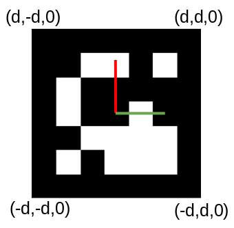
The diagram below shows the coordinate system of a fiducial marker, which has a length of 2d. The image coordinates (x, y) of each vertex correspond to a ray from the camera. The pose estimation code solves a set of linear equations to determine the world (X, Y, Z) coordinate of each of the vertices. From this, we obtain the transform of the fiducial’s coordinate system to the camera’s coordinate system Tfid_cam. This represents the pose of the marker in the camera’s coordinate system. Since we know the camera’s pose in the coordinate system of the robot, Tbase_cam, we can combine the two to determine the robot’s pose in the map, Tmap_base.
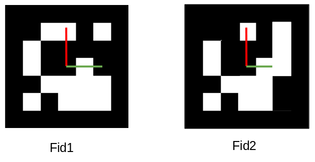
Construction of the map is performed by the fiducial_slam node. It performs Simultaneous Localization and Mapping (SLAM) based on the fiducial transforms. The mapping part requires that more than one marker is visible in an image. In the diagram below, two fiducials, fid1 and fid2 are shown. If fid1 is at a known pose in the world, Tmap_fid1 and we know the marker to camera transforms for both markers, we can compute the pose of fid2 thus:
Tmap_fid2 = Tmap_fid1 * Tcam_fid2 * Tfid1_cam
In this way, the map is built up as more fiducial pairs are observed, however multiple observations are combined.
Printing Fiducials
A PDF file containing a range of fiducial markers can be generated with a command such as:
rosrun aruco_detect create_markers.py 100 112 fiducials.pdf
The 100 and 112 specify the starting and ending numerical IDs of the markers. It is not important what these are (we recommend starting at 100), but it is important that each marker has a unique ID. This PDF file can be printed to produce the fiducials. They can be affixed to any convenient surface, such as a ceiling, where they will be viewed by the robot’s camera. They need to be at a sufficient that more than one is visible at a time.
Running the Software
The following command launches the detection and SLAM nodes on the robot:
roslaunch magni_nav aruco.launch
It should be run for the first time with at least one marker visible. A map (this is a file of fiducial poses) is created such that the current position of the robot is the origin.
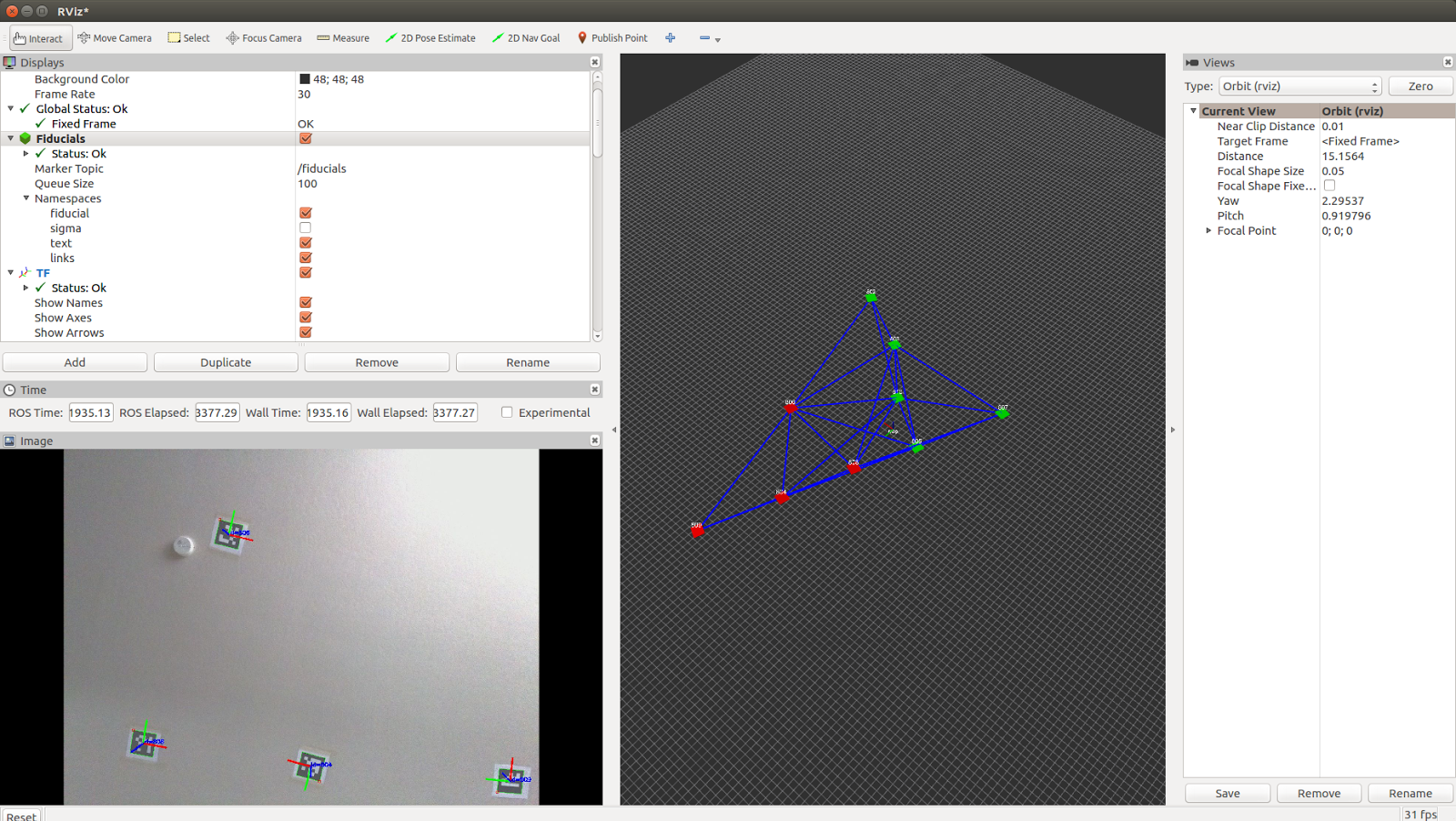
Using rviz to Monitor Map Creation
The following command can be used on a laptop or desktop to run the robot visualization tool, rviz.
For details on setting up your workstation to communicate with the robot (setting ROS_MASTER_URI), please refer to Workstation Setup.
roslaunch fiducial_slam fiducial_rviz.launch
This will produce a display as shown below. The bottom left pane shows the current camera view. This is useful for determining if the fiducial density is sufficient. The right-hand pane shows the map of fiducials as it is being built. Red cubes represent fiducials that are currently in view of the camera. Green cubes represent fiducials that are in the map, but not currently in the view of the camera. The blue lines show connected pairs of fiducials that have been observed in the camera view at the same time. The robustness of the map is increased by having a high degree of connectivity between the fiducials.